Fluent Meshing|07 多孔介质网格

本文摘要(由AI生成):
本案例演示了使用Fluent Meshing中的FTM流程创建多孔介质区域的过程。首先导入几何模型,描述几何并创建多孔介质区域,通过调整坐标和参数实现网格过渡。接着识别计算区域,进行泄漏检测并更新区域设置。控制网格尺寸,生成面网格和体网格,并插入子节点分离接触面。最后,在Fluent中设置多孔介质参数、入口速度和出口边界,并计算流线分布。
本案例演示利用Fluent Meshing中的FTM流程创建多孔介质区域。
1 导入几何模型
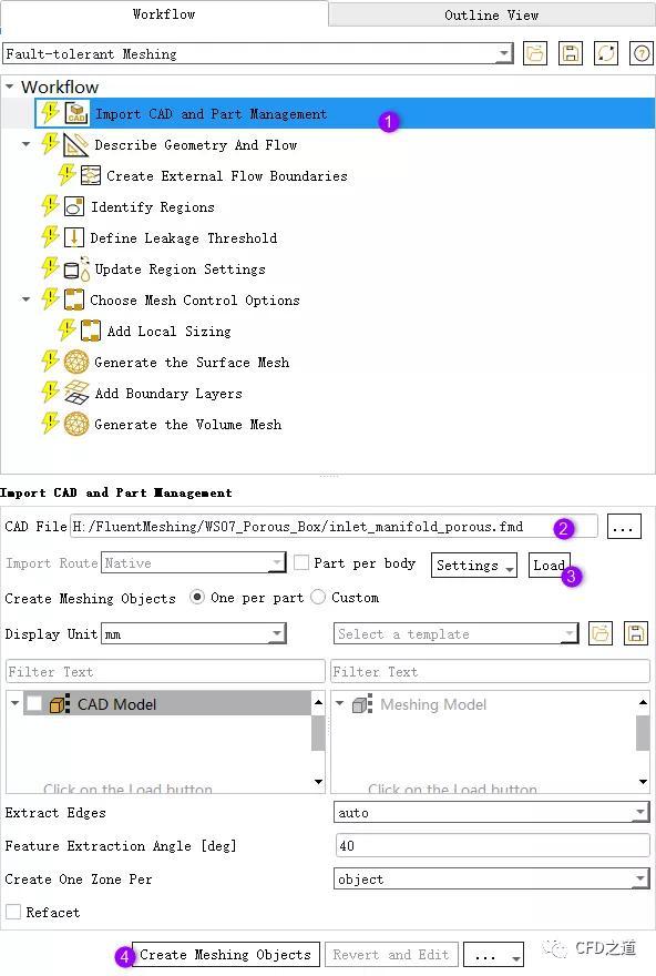
启动Fluent Meshing,如下图所示,采用默认参数导入计算模型inlet_manifold_porous.fmd
2 描述几何
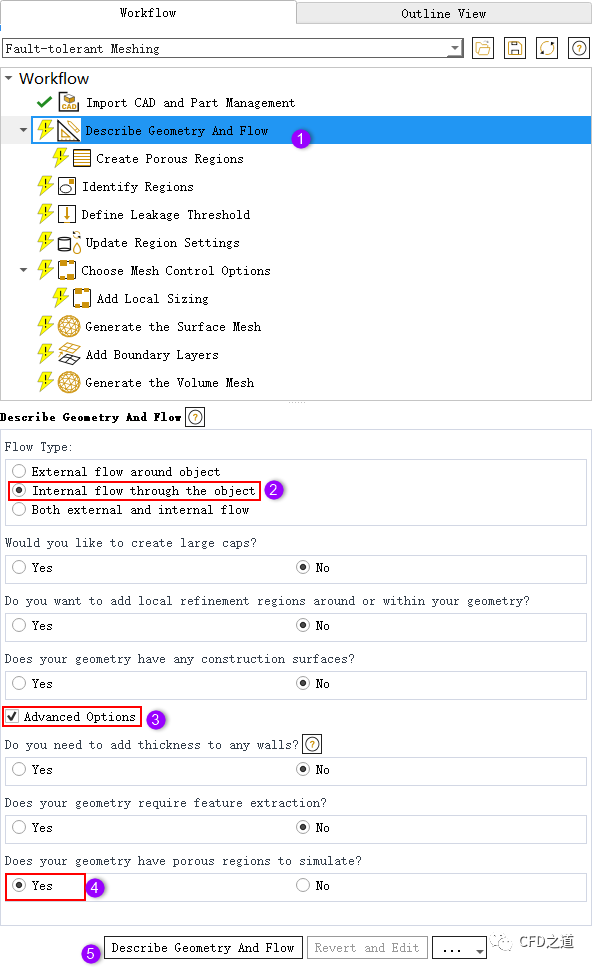
选择模型树节点Describe Geometry And Flow,按下图所示顺序选择参数,注意图中步骤4的选项
3 创建多孔介质区域
选中流程节点Create Poroous Regions
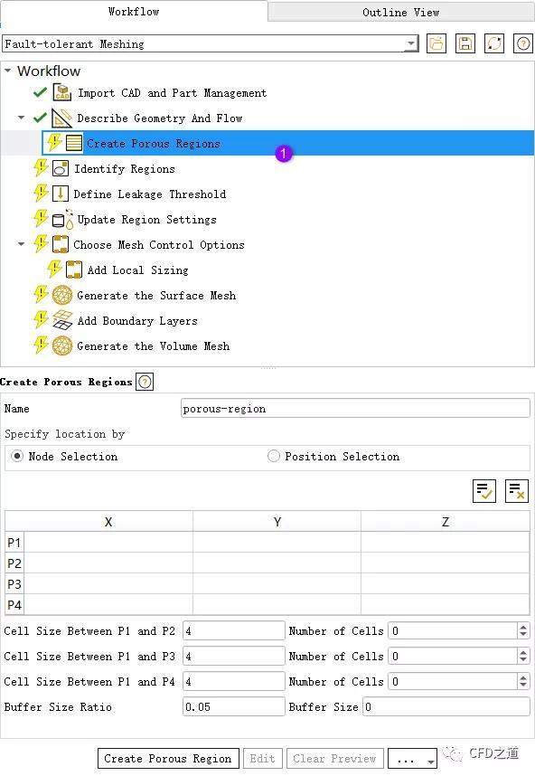
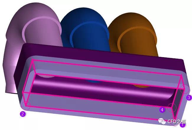
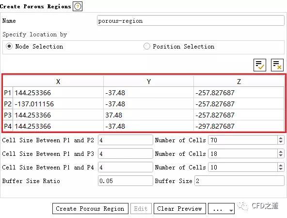
按下图所示顺序选择节点,选择完毕后会如图所示高亮显示识别的区域,注意节点的选择顺序
选择完毕后参数设置窗口会显示识别的4个点的坐标值,如下图所示
修改这4个点的Z坐标,如下图所示
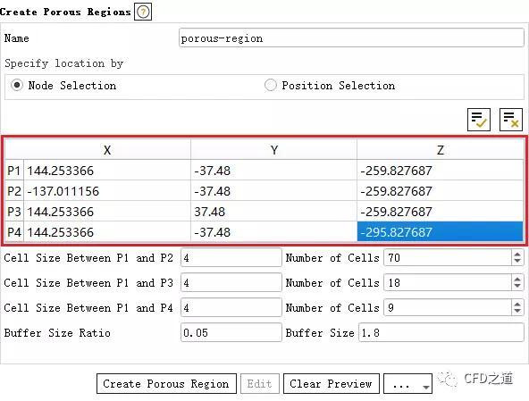
往里面缩进2 mm是为了生成网格过程中更好地实现网格过渡

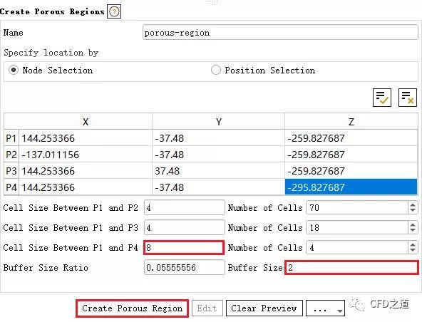
如下图所示修改框选位置的参数,注意参数Buffer Size与前面缩进的尺寸保持一致
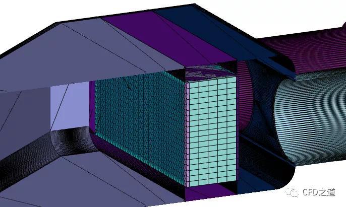
多孔区域网格如下图所示。
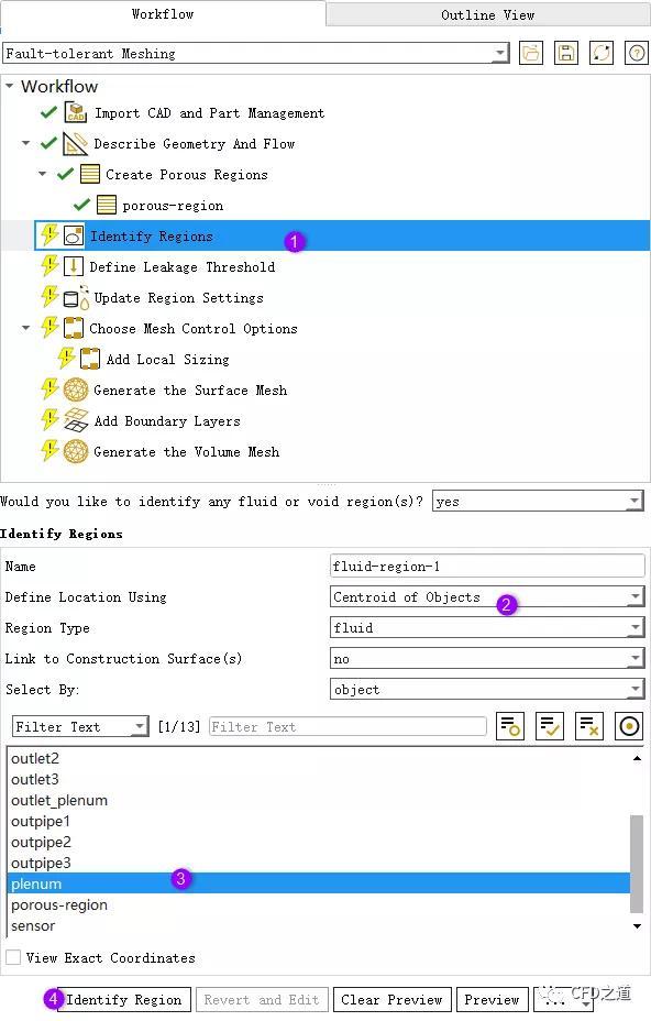
4 识别计算区域
选择流程节点Identify Regions,如下图所示选择参数。这里也可以在图形窗口中直接选择几何模型
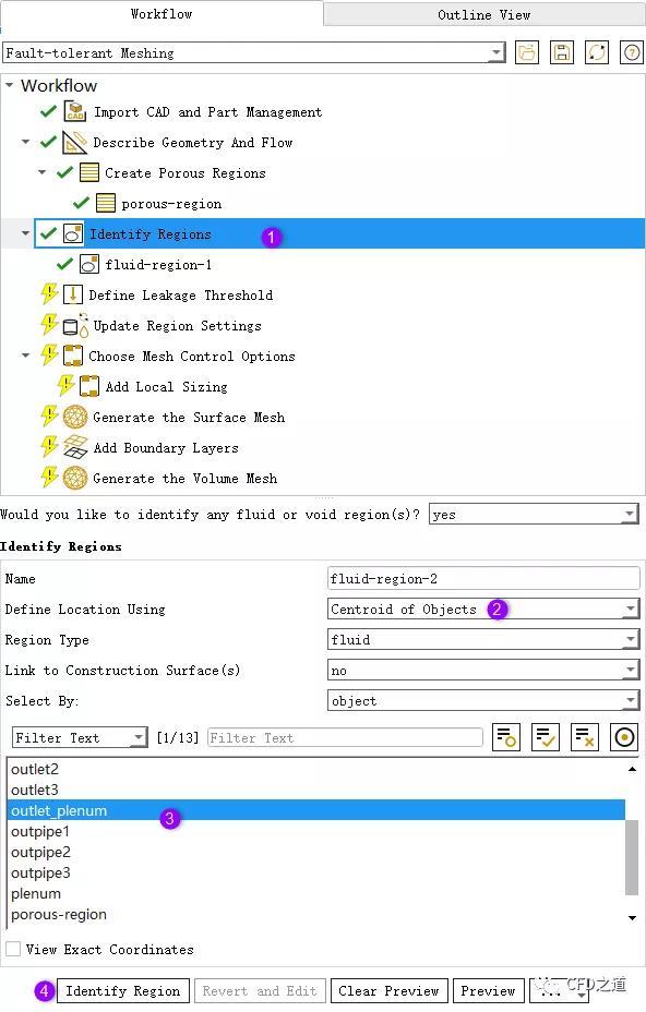
相通方式选择另外一个区域,如下图所示
5 泄漏检测
选择流程节点Define Leakage Threshold,如下图所示采用默认设置
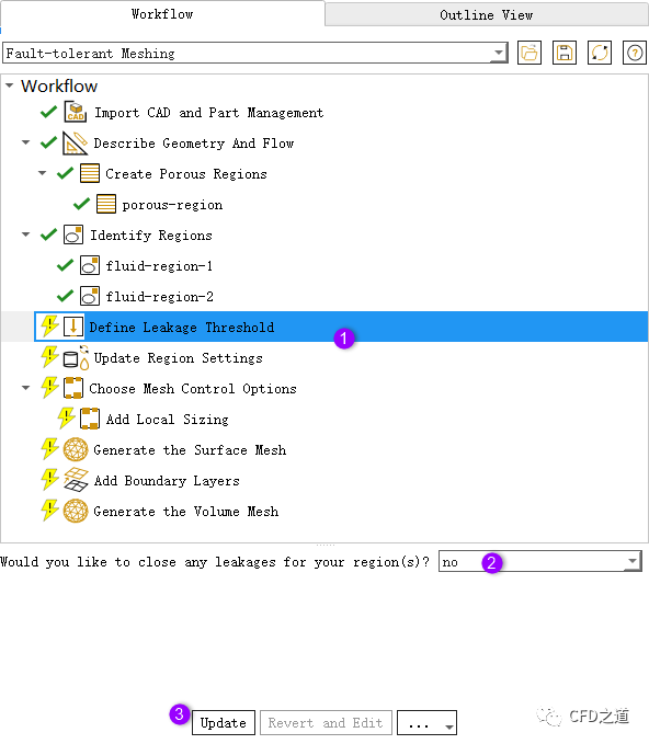
注:注:本例几何为封闭几何,无需进行泄漏检测工作。
”
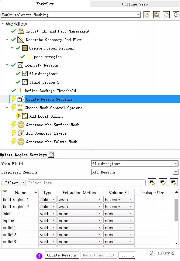
6 更新区域
进入Update Region Settings节点,采用默认设置
7 网格尺寸控制
Choose Mesh Control Options节点采用默认设置
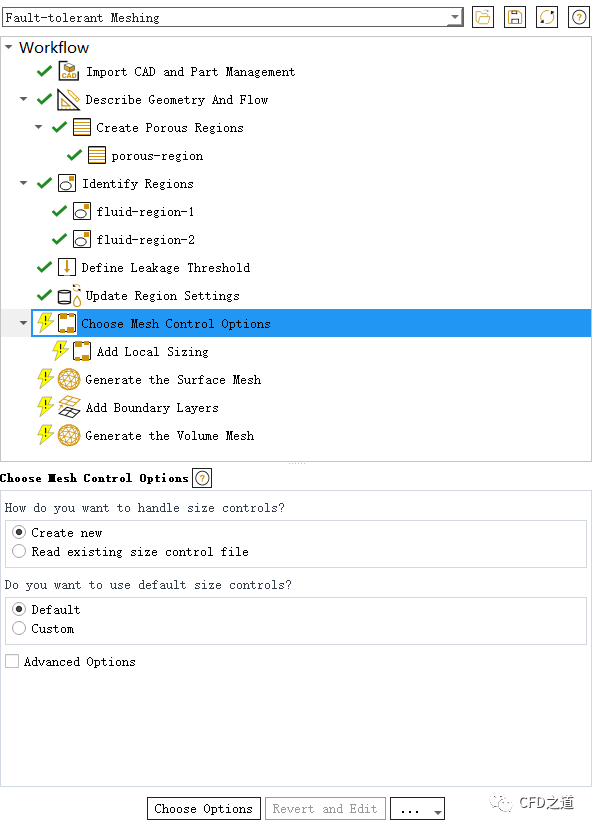
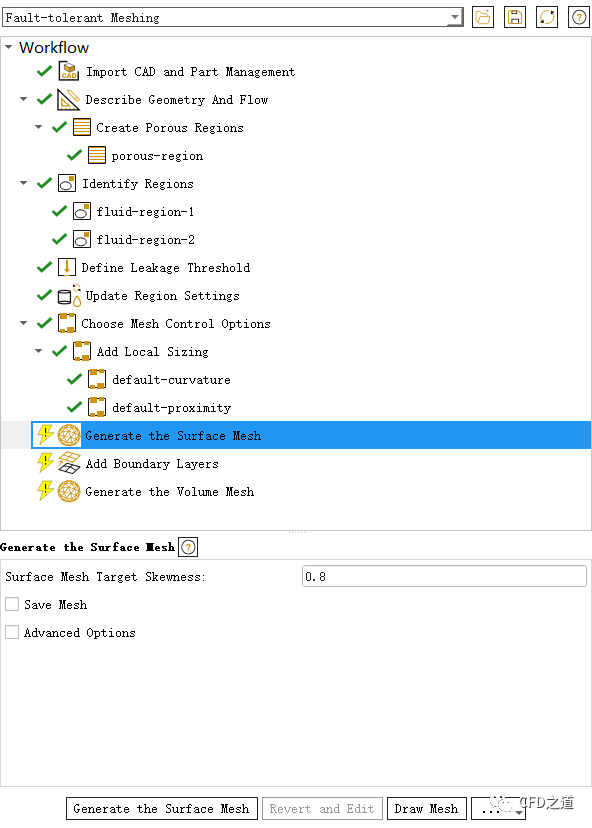
8 生成面网格
进入Generate the Surface Mesh节点,采用默认设置生成面网格
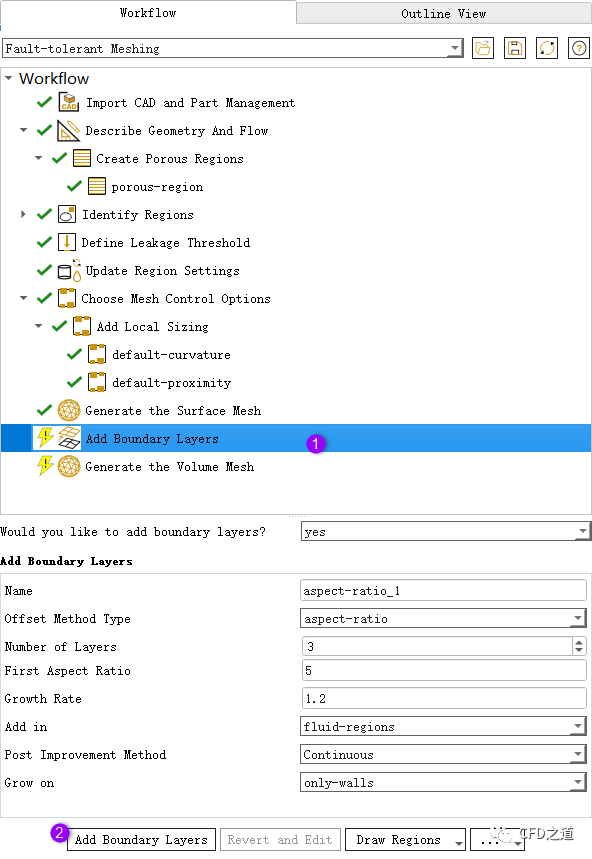
9 边界层网格参数
边界层参数采用默认设置,如下图所示
10 生成体网格
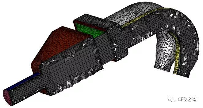
如下图所示生成体网格
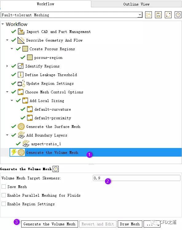
完成的体网格如下图所示
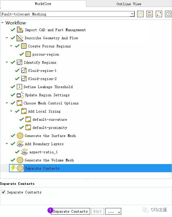
右键选择节点Generate the Volume Mesh,点击菜单项Insert Next Task → Separate Contacts插入子节点
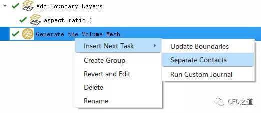
采用默认设置分离接触面,如下图所示
注:注:分离接触面之后才会生成Interface边界
”
保存计算网格,进入Solution模式
11 Fluent设置
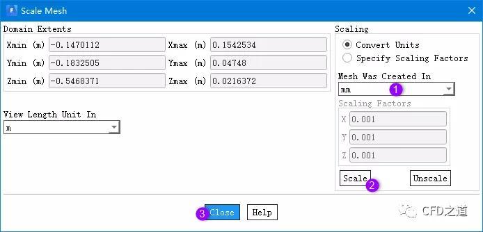
缩放几何为mm
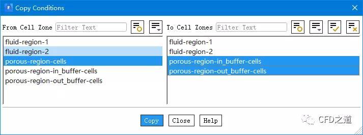
如下图所示设置多孔介质参数
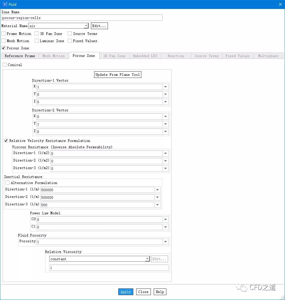
三个多孔介质区域(主区域加两个buffer区域)
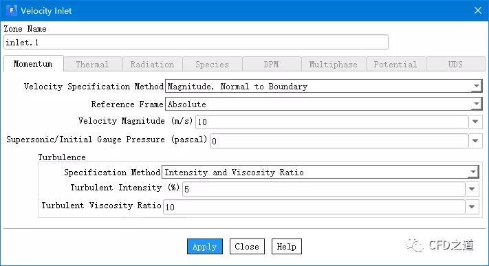
设置入口10 m/s
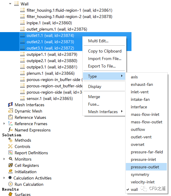
指定出口边界为压力边界
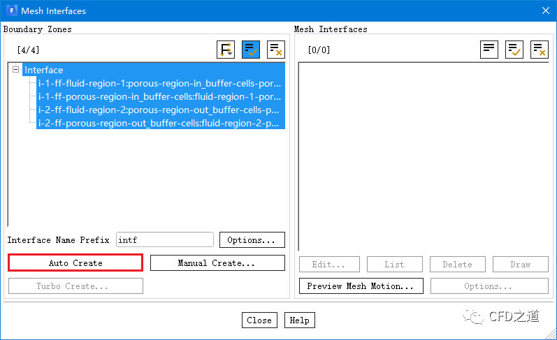
自动方式创建interface
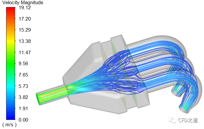
计算得到的流线分布
登录后免费查看全文
附件
免费链接.txt
著作权归作者所有,欢迎分享,未经许可,不得转载
首次发布时间:2020-07-31
最近编辑:11月前

博士
|
教师
探讨CFD职场生活,闲谈CFD里外


相关推荐
最新文章
热门文章
