ANSYS Maxwell2020R1 – What’s New

2020R1 – What’s New
New Release Capabilities
1 Element-based Volumetric Harmonic Force Coupling
•Maxwell Eddy Current or Maxwell Transient to ANSYS Harmonic Response
•Uses Non-uniform Discrete Fourier Transform to covert to Freq domain for Harmonic Response and Harmonic Acoustics

2 2D Multi-slice Model for Object-based Harmonic Force Coupling
•Quasi-3D effects considered by 2D multi-slice model
•Object based harmonic force
•Harmonic force generated for full 3D mechanical (2D skew model is not supported in mechanical)

2D Multi-slice Model for Object-based Harmonic Force Coupling.

Enhanced Capabilities
1 Demagnetization Coefficient Plot in 2D and 3D
•Demagnetization coefficient definition:
Demag_coef[%] = Br1/Br0*100%
Demag_coef = 1, no any demagnetization at the location
Demag_coef = 0, fully demagnetized at that location
•Outputs:
•Demag_coef shade plot over all nonlinear permanent magnets
•Demag_coef curve with time at specific location using expression cache
•Demagnetization percentage statistics curves with time by accounting for all magnet volume associated with Demag_Coef above threshold from 0.1 to 0.9 with step 0.1 respectively (total 9 curves)

Demagnetization coefficient shade plot


Demag coefficient at specified location vs time
Demag percentage statistics curve vs time

2 Litz Wire Modeling
•Simple conductor considers individual strands
•New material composition: Litz Wire
•Wire type: Round, Square, Rectangular
•Considers additional ohmic loss due to skin and proximity effects
•Reports additional loss curve: StrandedLossAC


3 AC Winding Loss in Machine Toolkit
Stator winding loss:
P_copper=P_dc+P_ac
•DC winding loss:P_dc=I_rms^2 (R_a+R_b+R_c )
•AC winding loss:P_dc=〖3I〗_rms^2 R_ac=〖3I〗_rms^2 R_ac0 (f/f_0 )^2 (k_ξ/k_ξ0 )
where Rac0 is the user-defined ac-resistance at reference frequency, and
k_ξ=3/2ξ (sinhξ-sinξ)/(coshξ-cosξ), ξ=a√(πfμ_0 σ)
a is the width/diameter of the winding strand conductor.
Rac0, a, σ, and f0 are inputs in the machine toolkit UI.
Winding loss with dc loss only (Rdc = 0.015 Ω)

Winding loss with dc & ac losses (Rac = 0.003 Ω at 60 Hz)

4 New Machine Type: Synchronous Reluctance Machine
•The sweeping variables are phase RMS current, angle Gamma and Speed
•Auto angle alignment
•Periodic and half-periodic TDM supported
•DQ-axis component calculation: d-axis rotor has the largest permeance/inductance


6 Postprocessing Harmonic Force Density in Maxwell 2D/3D Transient
•Automatic FFT creates 2D reports: vector or amplitude at specified frequency – phase angle
•Harmonic force density reports and plots in Transient time-domain solver


BETA Capabilities
1 Maxwell 3D Transient - A-Phi formulation [Beta]
•Formulated using the A and electric scalar potential φ
•The first order edge elements for magnetic vector potential
A and the second order nodal elements for electric scalar potential φ
•Multi-terminal conductors support sources of various types on a single conduction path
•Partial inductance calculated (not loop)
•J and E fields calculated directly because it is the first order approximation Applicable for bus bar thermal problems where multiple terminals can be excited with arbitrary waveforms and the power loss can be
B=∇×A
B=μH
J=σ(-dA/dt- ∇ φ)
∇×μ^(-1) ∇×A=-σ dA/dt- σ∇ φ+∇×H_c
∇⋅(-σ dA/dt- σ∇ φ)= 0
Planned for future releases:
•External Circuit

2 Auto Partial Simulation for Full Rotational Machine [Beta]
•Full-model
Pros: easy to setup; better field visualization to understand physics
Cons: very large computation time
•Manually created reduced-model by applying planar master/slave boundary
Pros: much less computation time
Cons: not easy to setup; less intuitive from reduced-model visualization
•Auto partial model creation, meshing, simulation, post-processing with non-planar matching boundary
Preserve and combine all pros eliminating all cons from both full model and reduced model
•Applicable to non-skewed machine model with/without clone mesh [Beta]


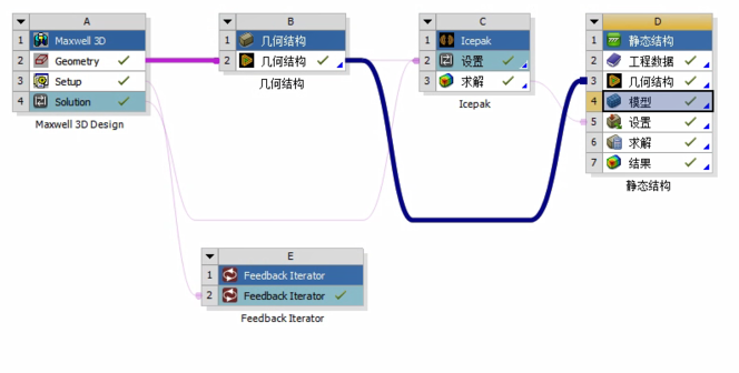
3 Mechanical Design Type in Electronics Desktop [Beta]
•Mechanical Solvers: Modal and Thermal
•Supports 2-way coupling with electromagnetics
•Integrated UI: Modeler, Scripting, Optimetrics, Post Processing •Mesh: AEDT Classic/TAU mesher or mesh linking from Maxwell
•Installation and licensing (Icepak solver) in Electronics Desktop
Modal
NG


Thermal
4 Thermal Simulation for Electric Motor Design in AEDT [Beta]
•Mechanical Solvers: Modal and Thermal
•Supports 2-way coupling with


上海艾羽信息科技有限公司是一个以CAE软件销售、技术咨询及服务,仿真咨询及规划布局为一体的高科技公司。
作为ANSYS的合作伙伴,艾羽致力于将ANSYS推出的产品,通过业界性能颇佳、颇丰富的工程仿真软件产品组合帮助客户解决复杂的仿真难题。力求与ANSYS一起,共同为中国制造业提供先进的仿真技术,通过仿真技术支撑中国2025。