首页
发现
课程
培训
文章
案例
问答
需求
服务
行家
赛事
热门搜索
发布
消息
注册
|
登录
首页
/
文章
/
详情
SolidWorks Simulation 有限元分析实例练习(15):升降架分析
CAD-SW技巧
1年前
浏览2267
关注
问题描述:
一个载重为1800N的升降架承受一外部水压柱筒的作用,该水压柱筒与基座上的滑块相连。
点击
阅读原文
下载模型练习
1.打开零件。
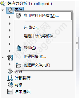
2.我们新建一个静应力分析的算例,如下图所示。
3.设置材料。我们需要为模型指定模型的材料属性。点击选中模型,鼠标右键选择“应用/编辑材料”。
指定模型的材料为铸造碳钢,如下图所示。
4.查看装配体的所有接触。下图红色部分有两个面是接触的。
5.因为我们对base的变形和应力不感兴趣,所有我们可以使用“不包括在分析中”命令来取消对base的分析。
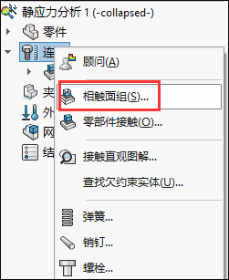
6.定义虚拟壁。选择“连接”鼠标右键选择“相触面组”。
类型选择为“虚拟壁”,选择slider底面作为组1,基准面base plane作为组2。
设置壁类型为“柔性”,设置摩擦系数为0.1,在轴向刚度中输入值:1.6537E+013,正切刚度中输入值:6.2216E+012。
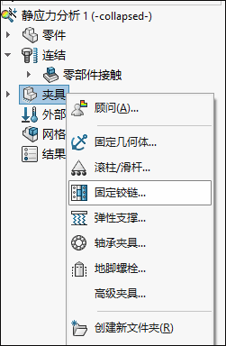
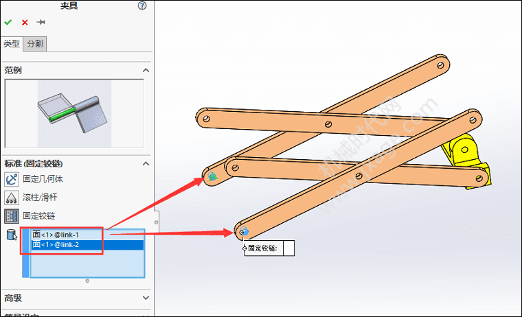
7.定义铰链约束。右键单击“夹具”并选择“固定铰链”。
选择如下图所示的两个内圆柱面定义固定铰链约束。
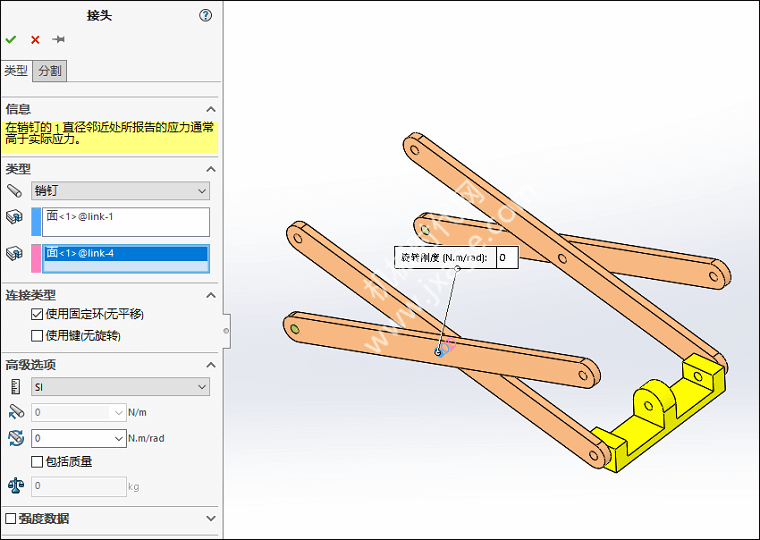
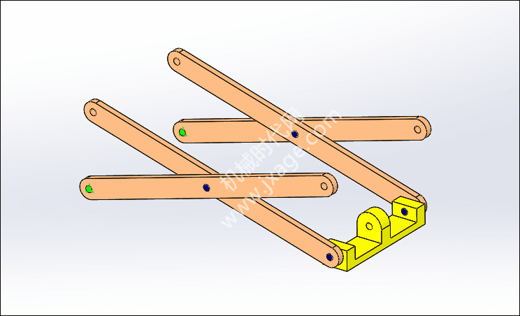
8.定义销钉接头。
在四个arm之间定义两个刚性的“销钉”接头。
在arm和slider之间定义两个刚性“销钉”接头。
9.对slider的圆柱面定义约束。
为了模拟水压柱筒提供的推力,选择连接slider的圆柱面应约束全局坐标X方向平移(与base平面平行)。
类型选择“使用参考几何体”,依次选择下面的slider内圆柱面和slider的侧面,并约束slider验证X方向的运动。
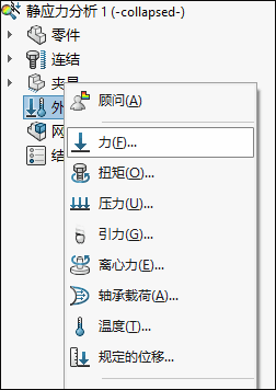
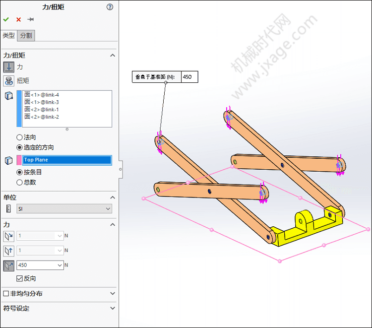
10.添加外部载荷。模型约束好之后,我们需要向模型施加外部载荷。选择外部载荷,鼠标右键选择“力”。
因为总载荷为1800N,因此每个arm上的力为450N。
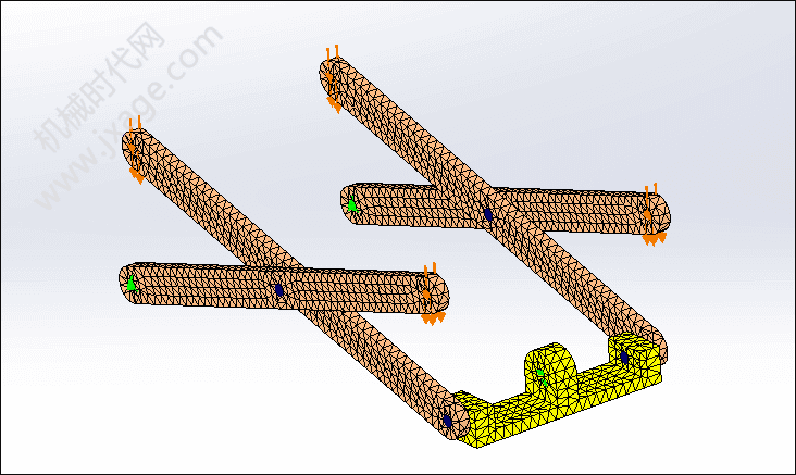
11.划分网格。
按照如下图所示进行设置。
网格划分完成之后如下图所示。
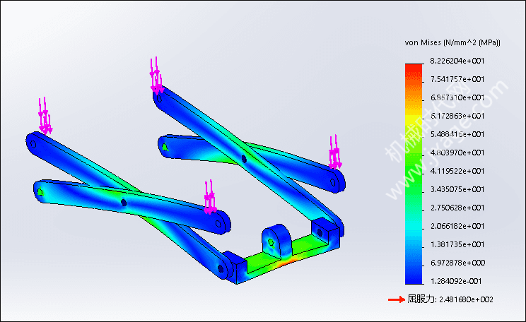
12.运行分析。我们可以看到最大von Mises应力值为82.3MPa,这个值远小于材料的屈服极限248MPa。
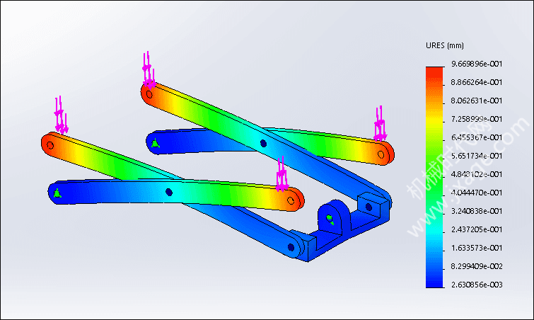
我们可以看到最大位移为0.97mm。
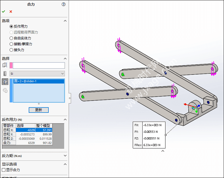
13.列举slider孔的反作用力。
选择“反作用力”,再选择slider的内圆柱面,我们可以看到slider约束圆柱面X方向的反作用力为6329N。
来源:SolidWorks技巧
登录后免费查看全文
立即登录
SolidWorks Simulation
SolidWorks
铸造
材料
著作权归作者所有,欢迎分享,未经许可,不得转载
首次发布时间:2023-05-05
最近编辑:1年前
CAD-SW技巧
本科
传播知识生态,赋能工业软件
关注
获赞 120
粉丝 174
文章 1716
课程 0
点赞
收藏
0/200
清空
提交
还没有评论
课程
培训
服务
行家
重庆大学王永艺博士后:基于RFPA的直接与间接拉伸下玄武岩柱力学、破裂及能量特征敏感因素研究
可试听
基于OpenFoam和AI机器学习14讲:使用人工智能建立流体力学中的数据驱动模型
云端CAE实战——OpenRadioss物品碰撞模拟分析
可试听
ALIAS汽车设计职业培训班-汽车A面从入门到精通(提高班-持续加餐更新)
相关推荐
课程
可试听
机械工程师实战课程74讲:零基础 30 天速成机械设计,直通企业级实战岗位
课程
可试听
材料非线性问题matlab有限元编程求解
课程
可试听
Solidworks2021从入门到实战
课程
可试听
Solidworks电机机座与端盖结构有限元分析9讲
最新文章
烧结银选购指南——甄嬛娘娘的“傻瓜式”避坑手册
悬置支架应力分析时为啥要输入材料的塑性曲线
JMPS期刊|超弹性材料中的耦合磁机械生长:仿生结构中的表面模式调制和形状控制
手把手教你做强制位移分析
特斯拉财报解读:2025Q1
热门文章
通用/泛亚/蔚来/弗迪/上海电驱动等百位新能源专家确认发言,易贸三电活动6月苏州见
【干货】SolidWorks克莱因瓶(图纸案例080期)
锂离子电池生产现场异物管控
ANSYS的断裂与失效计算方法简介
IAV:采用移动粒子半隐式(MPS)方法模拟电机中的自由流动冷却液的技术
其他人都在看
2024第四届中国算力之都·宁夏 工程仿真大赛CAE网格赛道【赛事通知】
故障诊断实验台 | BTS100轴承寿命预测故障实验台(16.8w)
固态电池碾压油车,轻松突破1000公里,石油税收大窟窿谁来填?
2024仿真秀618学习狂欢课程特惠大放送
高压条件下的氢气渗透及暴露聚乙烯的破坏-高压氢气装置用高分子材料的性能
VIP会员
学习计划
福利任务
下载APP
联系我们
微信客服
联系客服
人工服务时间为周一至周五的9:30-19:30
非工作时间请在微信客服留言
客服热线:
4000-969-010
邮箱:
service@fangzhenxiu.com
地址:
北京市朝阳区莱锦创意园CN08座
帮助与反馈
返回顶部