Maxwell帮助文档翻译-建模篇01

建模篇01
Drawing a Model
Maxwell2D/3D的学习资料一直都比较少,能用的参考书籍也只有一两本。但是其实最好的学习资料就是Help,之前的录制的视频教程也大都是帮助文档的二次整理。近期准备一点点翻译一下常用的一些部分,中英文放一起,希望给自认为看不懂英文帮助的小伙伴一个学习参考,其实你看得懂的,你就是懒而已,我信你。
现在翻译小队伍有两名成员,我们以每周5页的龟速缓慢地完成着这项漫长的FLag,如果你也想加入,热烈欢迎,直接VX戳我即可。
After you insert a design into the current project, you can draw a model of the electromagnetic structure. The general strategy is to build the model as a collection of 3D objects. You can assign any single material to each 3D object.
将设计插入当前项目之后,就可以绘制电磁结构的模型了。一般的策略是将模型建成三维对象的集 合。你可以为每个3d 对象分配一种材料。
You can create 3D objects by using the modeler’s Draw commands or you can draw 1D and 2D objects, and then manipulate them to create 3D objects. Objects are drawn in the 3D Modeler window. You can also import objects from other systems.
可以使用Modeler中的 Draw 命令来创建3d 对象,也可以通过绘制1d 和2d 对象进而创建3d 对象。对象在3D Modeler 窗口中绘制。你也可以从其他系统导入几何对象。
To open a new 3D Modeler window, do one of the following:
要打开一个新的3d Modeler 窗口,请执行以下操作之一:
●Insert a new design into the current project.
在当前项目中插入一个新的设计。
●Double-click a design in the project tree.
双击项目树中的设计。
If a 3D Modeler window is not open, do one of the following:
如果3D Modeler 窗口没有打开,请执行以下操作之一:
●On the Maxwell menu, click 3D Model Editor.
在 Maxwell 菜单上,单击3D Model Editor。
●Right-click the design name in the project tree, and then click 3D Model Editor on the shortcut menu.
右键单击项目树中的设计名称,然后在快捷菜单中单击3D Model Editor。
The model you draw is saved with the current project when you click File>Save.
当您单击 File > Save 时,您绘制的模型将与当前项目一起保存。

注意: 如果你通过远程桌面访问你的机器,如果 Maxwell 正在运行并且打开了一个或多个建模窗口,此时这些建模窗口将自动关闭。消息管理器窗口将显示一条消息,提示你Maxwell 关闭了建模窗口。
When working with multiple projects, or when a project has multiple designs, you may have multiple Modeler windows available. To switch to the modeler window associated with a specific design:
当处理多个项目时,或者当一个项目有多个设计时,您可能有多个 Modeler 窗口可用。使用以下操作用来切换到与特定设计相关的 modeler 窗口:
1.In the Project Manager window, select the Design of interest.
在 Project Manager 窗口中,选择感兴趣的 Design。
2.Click Maxwell3D Model Editor to focus the modeling window on the selected design.
单击 Maxwell3D Model Editor 将建模窗口集中在所选设计上。

注意: 如果菜单命令不可用,那么选择的设计已经在建模窗口中。
Drawing Objects绘制对象
You can draw one-, two-, or three-dimensional objects using the Draw commands. You can alter objects individually or together to create the geometry of your structure. In the Tools>Modeler Options, Drawing tab, you can set a default to either draw objects directly with the mouse or by invoking a Properties dialog in which you can enter the values for the object dimensions. The Dialog mode drawing feature works with the equation based line, and all two and three dimensional objects. You can toggle to Point mode via the F3 function key and to Dialog mode via the F4 function key. When you use the Dialog mode for drawing objects the Edit property of new primitives setting is ignored.
●可以使用 Draw 命令绘制一维、二维或三维对象,可以单独或者一起改变对象来创建几何结构。
●在 Tools > Modeler Options,Drawing 选项卡中可以设置默认操作(找不到这个操作),来设置是使用鼠标直接绘制对象,还是通过调用 Properties 对话框来输入对象尺寸数值。
●Dialog 模式绘图功能可以绘制基于方程的直线、所有的二维和三维对象。
●你可以通过 F3功能键切换到 Point 模式,通过 F4功能键切换到 Dialog 模式。
●当你使用 Dialog 模式绘制对象时,会忽略Edit property of new primitives设置的属性。
One-dimensional (1D) objects in the modeler include straight line, arc line, center-point arc, and spline segments, or a combination of these - called polylines. One-dimensional objects are open objects; their boundaries do not enclose a region, unless you connect their endpoints. They have length, but no surface or volume. Generally they are used as temporary objects from which to create 2D objects.
●Modeler中的一维(1D)对象包括直线、弧线、中心点弧线和样条段,或以上线条的组合-称之为多段线。一维对象是开放对象; 它们的边界无法包围一个闭合区域(除非把他们的端部进行连接)。1D对象有长度,但没有表面或体。一般来说,1D对象被用作临时对象,以便从中创建2d 对象。
Two-dimensional (2D) objects in the modeler include objects such as equation based surfaces, rectangles, ellipses, circles, and regular polygons. Two-dimensional objects are closed sheet objects; their boundaries enclose a region. You can create 2D sheet objects by covering the enclosed region. In many applications (FSS, antennas) it is essential to calculate net power flow through a surface.
Modeler中的二维对象包括基于方程的曲面、矩形、椭圆、圆和正多边形。二维物体是封闭的片状物体,它们的边界包围着一个区域。你可以通过覆盖封闭区域来创建二维图形对象。在许多应用中(FSS,天线) ,计算通过表面的净功率流是必不可少的。
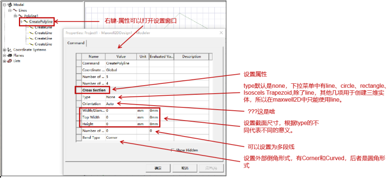
ou can also edit the properties of a polyline from the history tree to assign it a Cross Section property as line or rectangular. If you then assign it either a height or a width, the polyline becomes a sheet object.
通过编辑历史树中多段线的属性,可以把它的将 Cros Section 属性分配为直线或矩形。如果分配一个高度或宽度,多段线就会变成一个面体。
译者注解:
By default, the history tree organizes sheet objects according to their boundary assignments. To change this, select the Sheets icon, and right-click to display the Group Sheets by Assignment check box. Within the calculator sheet objects are listed under surface.
默认情况下,历史树会根据施加的边界类型来整理sheet对象。想修改整理方式的话,可以 Sheets 图标上右击显示 Group Sheets by Assignment 复选框。在场计算器工作表中,sheet对象被列surface下面(不是很理解)。
译者注:调整整理方式的操作路径为:Sheets上右键-History Tree Layout,然后可以看到有多重整理方式,可以按照需要选择。
Three-dimensional (3D) objects in the modeler include objects such as boxes, cylinders, regular polyhedra, cones, spheres, torii, and helices. These objects have boundaries that enclose a region with volume.
三维(3D)对象包括立方体、圆柱体、规则多面体、锥体、球体、圆环和螺旋等对象。这些对象具有边界,用体积包围着一个区域。
You can create 3D objects by manipulating 2D objects along a plane or by using the appropriate Draw commands. You can also edit the properties of a polyline from the history tree to assign it a Cross Section property as circle rectangular. If you then assign it an appropriate diameter or both height or a width, the polyline becomes a 3D object.
你可以通过在平面上操作2d 对象或者使用合适的 Draw 命令来创建3d 对象。你也可以从历史树中编辑一条多段线的属性,将它分配一个横截面属性作为圆形或矩形。如果你给它一个合适的直径或者高度和宽度,多段线就会变成一个3d 物体。
By default, the history tree organizes 3D objects by material. To change this, select the Objects icon, and right click to display the History Tree Layout Commands. You can also use Group Commands for Modeler Objects.
默认情况下,历史树按照材料类型整理3d 对象。要改变这一点,选择 Objects 图标,然后右击显示 History Tree Layout Commands。你也可以使用Group Commands for Modeler Objects。
While you draw objects you can also:
当你绘制物体的时候,你也可以:
●Select Movement Mode as 3D, In Plane, Out of Plane, Along X, Y or Z axis.
选择运动模式为3d,平面,平面外,沿 x,y 或 z 轴。
●Select Grid Plane as XY, YZ, or XZ.
选择网格平面为 XY,YZ,或 XZ。
●Set Snap Mode
设置 Snap 模式
●Set Reference Point for the movement mode
为运动模式设置参考点
●Adjust the View
调整视角
After you draw an object in the 3D Modeler window, you can modify the object’s properties, such as its position, dimensions, or color, in the Properties dialog box. Most object properties can be assigned to variables that can then be manipulated during the solve to test their effect on the solution.
在3D modeler 窗口中绘制对象后,可以在“属性”对话框中修改对象的属性,例如它的位置、尺寸或颜色。大多数对象属性可以分配给变量,这些变量可以在求解过程中进行修改,以测试它们对解决方案的影响。

注意: 如果您通过远程桌面访问您的计算机,如果 Maxwell 正在运行,一个或多个Modeler 窗口打开时,这些 modeler 窗口会自动关闭。消息管理器窗口会显示一条消息,指示 Maxwell 关闭了建模窗口。
Drawing a straight Line segment
绘制直线段
To create an object with one or more straight line segments, use the Draw>Line command.
若要创建具有一个或多个直线段的对象,请使用 Draw > Line 命令。
1.Click Draw>Line .
点击 Draw > Line。
2.Select the first point of the line in one of the following ways:
以下列其中一种方式选择线的第一个点:
●Click the point.
点击这个点。
●Edit the point’s coordinates in the X, Y, and Z boxes in the status bar.
在状态栏的 x、 y 和 z 框中编辑点的坐标。
To delete the last point that was entered, click Undo Previous Segment on the shortcut menu. After using the undo feature, you can also use Redo Previous Segment on the shortcut menu.
要删除输入的最后一个点,请单击快捷菜单上的“Undo Previous Segment”。使用撤销功能后,你也可以在快捷菜单上使用Redo Previous Segment。
3.Select the endpoint of the line by clicking the point or typing the coordinates in the text boxes in the status bar.
通过点击点或者在状态栏的文本框中键入坐标来选择线的终点。
The endpoint serves as the start point for a subsequent line segment.
上一条线段的的终点将会作为后续线段的起点。
To delete all points and start over, press ESC or click Escape Draw Mode on the shortcut menu.
若要删除所有点并重新开始,请按 ESC 或单击快捷菜单上的 Escape Draw Mode。
4.Complete the line in one of the following ways:
用下列方法之一完成绘制直线:
Double-click the endpoint.
双击终点。
Click Done on the shortcut menu.
在快捷菜单上单击“Done”。
Press Enter.
按回车。
If the Modeler option for editing properties of new primitives is checked, the Properties dialog box appears, in which you can modify the object’s attributes. Those listed under the Command tab describe the commands used to create the object. These commands also appear in the History tree. The Properties listed as line attributes include Name, Orientation, whether a Model object, whether to Display Wireframe, Color, Transparency, and whether to Show Direction as arrows. The Show Direction property is most helpful to unambiguously show the line start orientation when plotting fields along a line.
如果Modeler option for editing properties of new primitives是选中状态,绘制完直线后将直接出现“属性”对话框,您可以在该对话框中修改对象的属性。在 Command 选项卡下列出的命令描述了用于创建对象的命令。这些命令也出现在历史树中。线段的属性包括 Name(名称)、 Orientation(坐标系)、是否是 Model 对象、是否显示 Wireframe(线框)、 Color(颜色)、 Transparency(透明度) 以及是否将 Direction 显示为箭头。Show Direction 属性有助于在沿着一条线绘制场结果时来显示线段的起始方向。
译者配图:

5.Click OK to close the Properties dialog.
单击 OK 关闭 Properties 对话框。
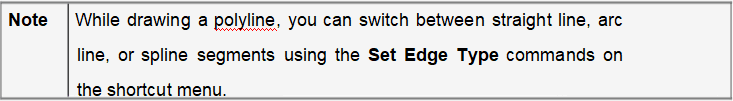
注意: 在绘制折线时,可以使用快捷菜单上的 Set Edge Type 命令在直线、弧线或样条线之间切换。
Drawing a Three-Point Arc Line
绘制三点弧线
In the modeler, a three-point arc line segment is an arced line defined by three points on its curve.
Use the Draw>Arc>3 Point command to create a polyline object with one or more arc line
segments.
在建模器中,三点弧线段是由其曲线上的三个点定义的弧线
使用Draw > Arc > 3 Point命令来创建一个带有一条或多条弧线的折线对象
1.Click Draw>Arc>3 Point .
点击 Draw > Arc > 3 Point。
2.Select the start point of the arc in one of the following ways:
使用以下列其中一种方式选择弧的起点:
lClick the point.
点击第一个点。
lType the point’s coordinates in the X, Y, and Z text boxes in the status bar.
或者,在状态栏的 x、 y 和 z 文本框中键入点的坐标。
3.Select the midpoint of the arc by clicking the point or typing the coordinates in the X, Y, and Z text boxes in the status bar.
通过点击弧线的中点或者在状态栏的 x,y,z 文本框中输入坐标来选择弧线的中点。
To delete the last point that was entered, click Undo Previous Segment on the shortcut menu. After using the undo feature, you can also use Redo Previous Segment on the shortcut menu.
要删除输入的最后一个点,请单击快捷菜单上的“撤消上一段”。使用撤销功能后,你也可以在快捷菜单上使用重做上一段。
To delete all points and start over, press ESC or click Escape Draw Mode on the shortcut menu.
若要删除所有点并重新开始,请按 ESC 或单击快捷菜单上的 Escape Draw Mode。
4.Select the endpoint of the arc by clicking the point or typing the coordinates in the X, Y, and Z text boxes in the status bar.
通过单击点或在状态栏中的 x、 y 和 z 文本框中键入坐标来选择弧的终点。
The endpoint serves as the start point for a subsequent arc line segment.
这个终点同时也被作为后续弧线段的起始点。
5.If the endpoint is the last point of the polyline object, double-click the point to complete the polyline or click Done on the shortcut menu.
如果该终点是折线对象的最后一个点,请双击该点以完成折线或单击快捷菜单上的 Done。
If the Modeler option for editing properties of new primitives is checked, the Properties dialog box appears, in which you can modify the object’s attributes. Those listed under the Command tab describe the commands used to create the object. These commands also appear in the History tree. The Properties listed as line attributes include Name, Orientation, whether a Model object, whether to Display Wireframe, Color, Transparency, and whether to Show Direction as arrows. The Show Direction property is most helpful to unambiguously show the line start orientation when plotting fields along a line.
如果选中了Modeler option for editing properties of new primitives选项,线段绘制后将出现“属性”对话框,您可以在该对话框中修改对象的属性。在 Command 选项卡下会列出用于创建对象的命令。这些命令也出现在历史树中。列出的属性包括 Name(名称)、 Orientation(坐标系)、是否是 Model 对象、是否显示 Wireframe(轮廓线)、 Color、 Transparency 以及是否将 Direction 显示为箭头。Show Direction 选项在沿着一条线绘制场结果时极有助于明确线的起始方向。
6.Click OK. /
点击确定。
Based on the three points you specified, the modeler calculates the center point and radius of the arc and draws an arced line through the three points.
根据您指定的三个点,建模模块会计算出圆弧的中心点和半径,并通过这三个点绘制一条弧线。

注意: 在绘制折线时,可以使用快捷菜单上的 Set Edge Type 命令在弧线、直线或样条段之间切换


.jpg?imageView2/2/h/336)